
Commercial-First Planning
Projects are planned around property operations, infrastructure and the people responsible for the system.
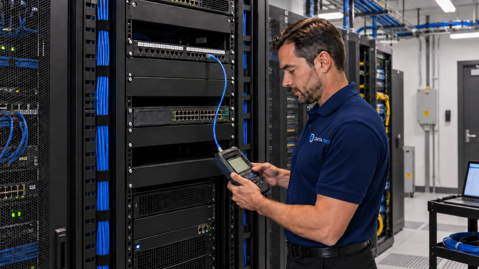
Commercial Camera Resource | Power and network infrastructure
Power over Ethernet carries data and DC power over one copper link, but a successful PoE camera design still depends on power class, switch wattage, cable-channel length, voltage loss, UPS strategy and verified port loading.
A 24-port switch may have enough ports but not enough PoE wattage for 24 heaters, illuminators or PTZ cameras at full load. PoE simplifies power distribution and restart control, but it concentrates camera availability on switches and upstream power and cannot ignore copper distance limits.
Projects are planned around property operations, infrastructure and the people responsible for the system.
Data Pro Communications operates under FL License #EC13016138.
Testing, labeling, credentials and known limitations are organized for the people who will operate and support the system.
Power over Ethernet carries data and DC power over one copper link, but a successful PoE camera design still depends on power class, switch wattage, cable-channel length, voltage loss, UPS strategy and verified port loading.
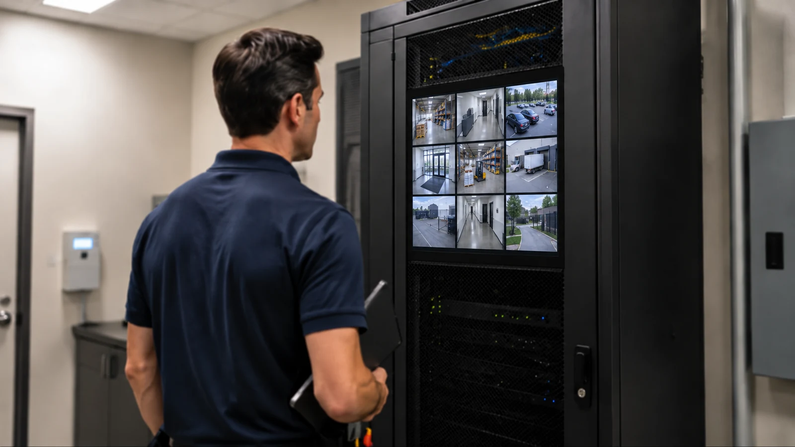
A network link can come up even when the port cannot supply the camera's required PoE class or auxiliary load, causing features or the device to fail under demand.
Enough open ports do not guarantee enough switch wattage. Startup load and high-power cameras can exceed the shared budget.
Excess copper length can reduce link margin and PoE performance, especially when patch cords and horizontal cable are counted separately.
Adding a midspan without documenting data path, power ownership and UPS coverage can create a service boundary that technicians cannot trace.
Backing up cameras without the recorder, switching or uplink can leave powered devices unable to record or communicate during an outage.
Unlabeled ports and untested loads slow fault isolation and conceal devices that negotiate less power than expected.
Match each camera and auxiliary feature to the supported port class and verify negotiated power under expected demand.
Add maximum device and startup loads across all ports, compare per-port and total limits and reserve realistic capacity for growth.
Measure horizontal cable plus patching against channel limits and verify PoE/load behavior at the far-end device.
Choose between a midspan and PoE switch by data ownership, power class, management, UPS coverage, port growth and service clarity.
Define which cameras, switches, recorder and uplinks remain available, required runtime and the recovery sequence after utility power returns.
Match camera and switch labels, confirm negotiated power and expected load, and test link stability and restart on each port.
A 24-port switch may have enough ports but not enough PoE wattage for 24 heaters, illuminators or PTZ cameras at full load.
A camera more than 100 meters from the switch may require fiber and a powered remote enclosure rather than an unsupported long copper run.
A PTZ may draw more power during startup, movement, heating or illumination than a basic fixed camera, so both its port class and the shared switch budget matter. Verify the camera's PoE class and maximum draw, the per-port limit and the switch's shared wattage before testing movement, heating and illumination together.
Backup power is useful only when the camera switch, recorder and required network links remain available for the intended runtime and recover cleanly. Define which switches, recorder and uplinks remain powered, calculate the required runtime, and observe shutdown and restart behavior when utility power is interrupted.
A long camera route should be measured end to end; copper Ethernet limits cannot be solved by increasing PoE wattage. Measure the permanent link and patching, certify the copper channel, and use fiber with powered equipment at the remote end when Ethernet distance or electrical isolation requires it.
A remote enclosure needs local power, environmental protection, fiber or copper termination, surge strategy, labeling and safe service access. Document local power, environmental rating, surge and grounding provisions, fiber or copper termination, port labels and the clearance needed for safe future service.
Record device-required class, negotiated power and auxiliary loads such as heaters, illuminators or motors for each camera port.
Compare per-port limits and the switch's total available PoE budget with maximum device and startup loads, UPS capacity and planned growth.
Approval of copper channel length requires route length, test results, protection, termination, environmental exposure and service access, plus a test result appropriate to the copper or fiber medium.
Document which device owns data and power, supported classes, management visibility, UPS source, port capacity, patching and failure isolation.
Calculate protected load and runtime for cameras, switches, recorder and necessary uplinks, then test shutdown alarms and restart sequence.
The record should connect camera ID, cable label, patch panel and switch port with negotiated power, observed load, link test and restart result.
PoE design joins camera power class, switch wattage, copper distance, uplink capacity and UPS coverage. A port or switch outage should be evaluated through the entire recording path so powered cameras are not left without a recorder or network connection.
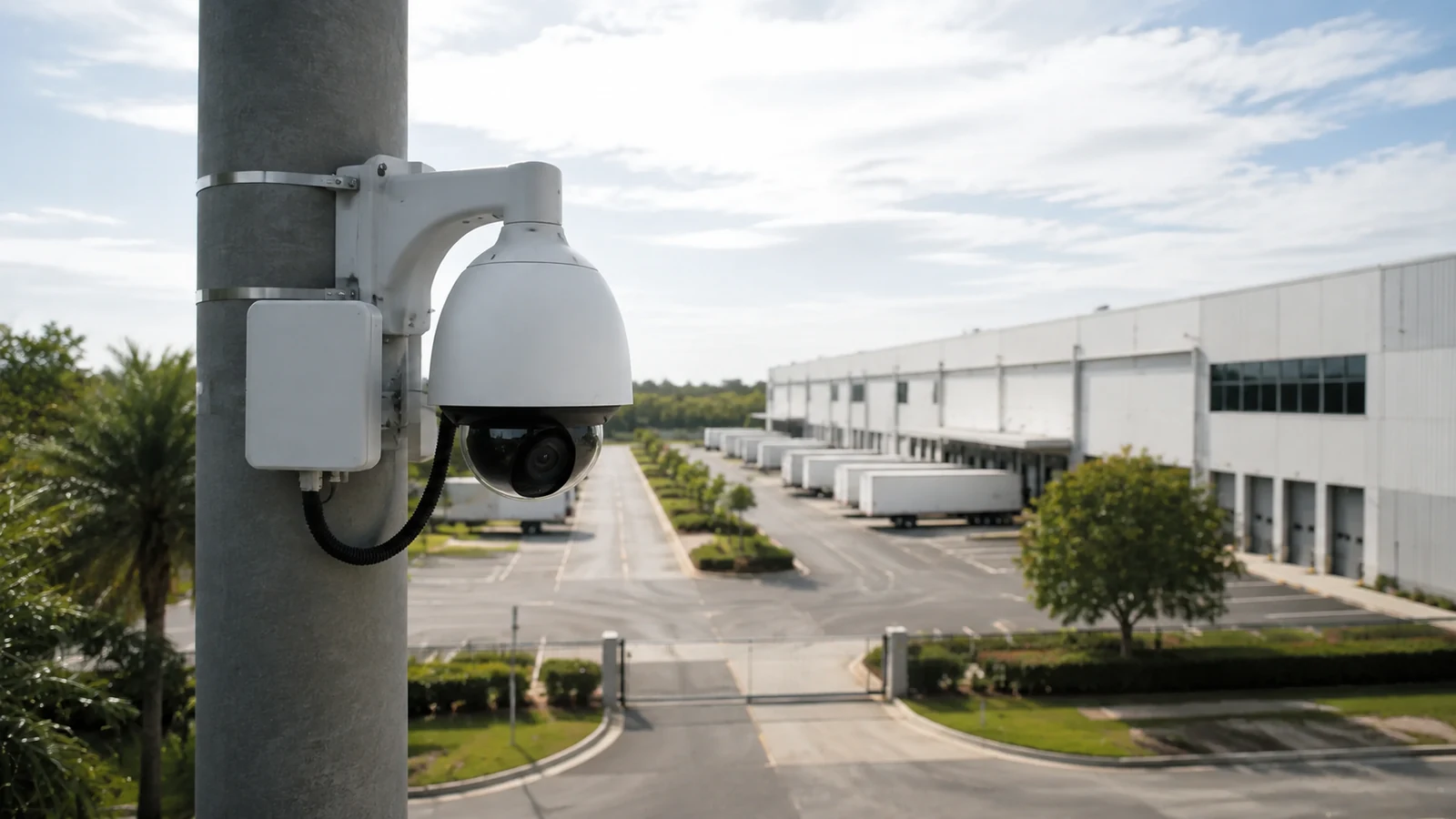
PoE planning for an Orlando camera system must account for device class, shared switch wattage, copper distance, uplinks and backup power across the complete recording path.
Structured-cabling, switch, UPS and network guides add context when PoE load or copper distance becomes the limiting part of a camera design.
Camera Services is relevant when PoE calculations lead to camera replacements, new switch ports, different mounting locations or changes to the recording design.
A field check is useful when switch location, cable length, UPS capacity or device load is uncertain enough to affect the PoE design.
A PoE design is sound when switch budget, cable length, per-port load and backup power support the actual cameras at full operating demand. Device class and switch capacity should be checked together rather than in isolation.
Check the required PoE standard and maximum draw for every camera, including heaters, illuminators or PTZ motors that can raise consumption during startup or operation.
Confirm the copper channel is within Ethernet limits and that each port can deliver the required class. Add device loads across the switch so the shared PoE budget is not exhausted when several cameras draw power at once.
Verify the switch uplink can carry the expected video traffic and decide which cameras and network devices need UPS-backed power. A powered camera is not useful if its switch or recorder loses power immediately.
Restart representative cameras and the PoE switch, then verify devices negotiate power, reconnect and resume recording. Testing should include higher-draw devices so startup demand does not reveal an undersized power budget later.
Cameras Orlando is operated by Data Pro Communications. Florida low-voltage work is performed under FL License #EC13016138.
The camera and any heater, illuminator or motorized feature must fit the switch or midspan class and budget, including startup demand.
Add the maximum required power for every connected device, allow for startup and future ports, compare per-port limits and confirm the total available budget.
For copper channel length, trace and label the route, inspect protection and termination, measure distance, use the appropriate copper or fiber test and confirm future service access.
A midspan can add power to an existing non-PoE data path, but the design still needs compatible power classes, switch capacity, UPS planning and clear ownership.
Define which switches, recorders and network links remain available, required runtime, battery monitoring and how the system recovers when utility power returns.
Labels should match camera and switch records; testing should confirm negotiated power, expected load, link stability and restart behavior for each port.
It is a fit when the property can support PoE power classes, switch wattage budget and copper channel length and the stated limitation is acceptable.
They can be reused when cable condition and distance pass testing, each port supports the required PoE class, the switch has enough total wattage and uplinks can carry the planned video streams.
Per-port class limits, an undersized shared wattage budget, startup demand or heaters, illuminators and PTZ motors can exceed available power even when the switch has enough open ports.
Connect the planned device load, exercise high-power camera functions and observe startup at the switch's maximum expected demand. Confirm the recorder and uplink remain available and that devices recover correctly after power returns.
Before adopting PoE camera design, verify PoE power classes, switch wattage budget and copper channel length at the property; a project consultation can resolve the remaining infrastructure or compatibility questions.