
Commercial-First Planning
Network planning evaluates active switching, uplinks, PoE and topology separately from the permanent cabling that carries the traffic.
Commercial Low-Voltage and Security Systems
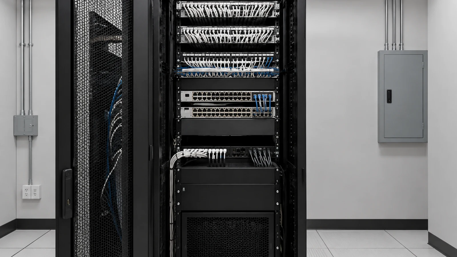
Commercial network infrastructure connects switches, uplinks and networked devices across telecom rooms and building areas. The design should account for port count, PoE demand, uplink capacity, topology, segmentation and the relationship between MDF/IDF rooms before active equipment is selected.
This page focuses on the active network layer. Structured cabling provides the physical copper links and fiber provides optical backbones; Network Infrastructure determines how those links are switched, segmented, powered and connected.
Network planning evaluates active switching, uplinks, PoE and topology separately from the permanent cabling that carries the traffic.
Data Pro Communications operates under FL License #EC13016138.
Port maps, uplink records and documented configuration responsibilities help IT teams understand what was installed and what remains under customer administration.
Commercial network infrastructure can include switch selection, PoE budgets, MDF/IDF topology, fiber or copper uplinks, VLAN/segmentation planning, rack capacity and power protection. The goal is reliable connectivity for the approved devices while keeping ownership of routing, security policy, internet services and customer IT administration clear.
A switch may have open ports but still lack the PoE budget or port type required by cameras, access points, phones and other powered devices.
IDF-to-MDF uplinks need enough capacity for aggregated traffic. A fast endpoint does not help if the upstream link is undersized.
Cameras, guest devices, business systems and building technology may need separate VLANs or policies. Segmentation should be coordinated with the customer IT/security model.
Rack units, patching space, UPS capacity, cooling and power availability can constrain switch selection and future growth.
Resiliency requires an actual design for redundant links, power or switching. Two cables or two switches do not automatically create failover.
Without port maps, VLAN notes and uplink records, future troubleshooting becomes slower and configuration ownership is unclear.
Count endpoints by speed and PoE class, then reserve practical capacity for growth rather than filling every port on day one.
Map which devices connect to each telecom room and how IDFs uplink to the MDF or other network core.
Match copper or fiber uplinks to expected aggregate traffic and the switch/transceiver architecture.
Coordinate VLANs, SSIDs and building-system segments with the organization responsible for network security and policy.
Review UPS, power circuits, switch stacking or other resilience features where operational requirements justify them.
Record switch names, ports, uplinks, VLAN responsibilities and configuration boundaries so support teams can work from a known baseline.
Office networks support users, phones, printers, conference-room devices and other endpoints with different bandwidth and policy needs.
Managed properties may connect cameras, access control, Wi-Fi and building systems while keeping those devices appropriately segmented from business traffic.
Campuses often rely on fiber uplinks between telecom rooms or buildings, making switch and transceiver architecture part of the backbone plan.
PoE budgets become important when switches power access points, cameras, phones or other devices, especially at high device density.
Separate VLANs or network policies can help organize tenant, guest, security and management traffic when coordinated with IT.
Larger environments benefit from consistent switch naming, port documentation and management responsibility across multiple telecom rooms.
Identify device count, link speed and PoE requirements by telecom room before sizing switches.
Confirm rack space, patching, power, cooling and cable management for new active equipment.
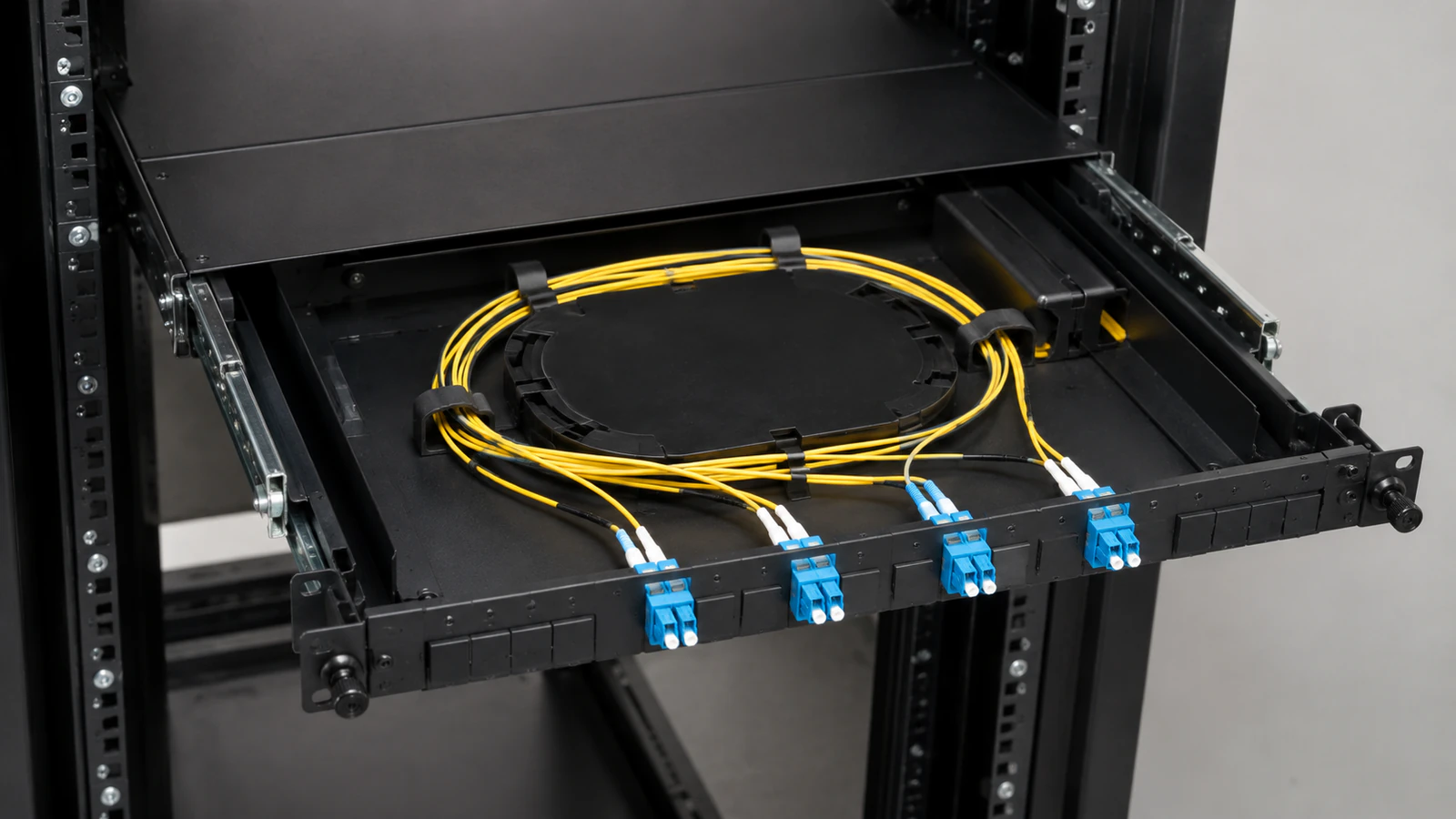
Verify whether each uplink uses copper or fiber, what speed it must support and which optics are required.
Coordinate VLANs, IP addressing, firewall or access policy with the customer IT team responsible for network security.
Review power circuits and UPS capacity so network availability goals are supported by actual electrical infrastructure.
Document whether routing, DHCP, DNS, firewall, internet service and remote administration remain with customer IT or are included in the approved scope.
Network Infrastructure is the active layer that many other solutions depend on. Structured cabling provides endpoint links, fiber provides high-capacity uplinks, and cameras, intercoms, access-control controllers or AV devices may consume ports, PoE and VLANs. Integration should therefore be expressed as specific network requirements, not a general promise that every system will share one network.
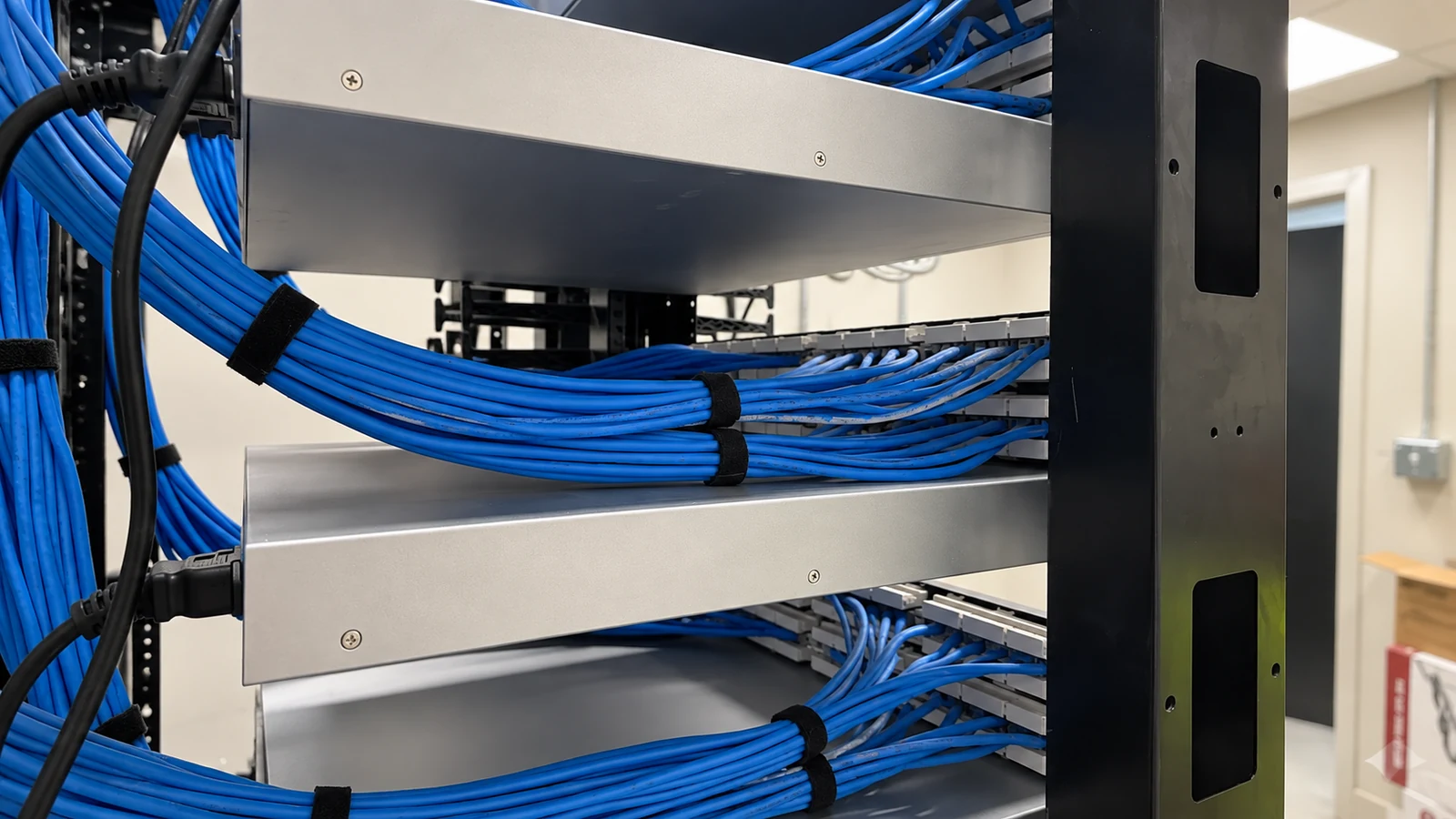
For Orlando commercial properties, the network plan should be based on the actual device inventory, telecom-room layout and customer IT model. Existing switches can be retained when port count, PoE, speed, management features and supportability fit the new requirements.
Use the Solutions hub when network work is one part of a broader building-technology project with cabling, fiber, cameras, access or AV.
A network site review can confirm telecom rooms, switch capacity, PoE load, uplinks and existing active equipment before replacement or expansion is planned.
Structured Cabling and Fiber Optic Services provide the passive copper and optical links that the active network switches use.
Offices may prioritize user and collaboration traffic; managed properties may combine business and building-system devices; multi-building sites may depend on fiber uplinks and distributed IDFs. Device mix and IT policy determine the appropriate topology.
Inventory endpoints, existing switches, PoE loads, telecom rooms, uplinks and customer-managed network services.
Develop the switch, port, uplink, VLAN/segmentation and power plan, with configuration responsibilities clearly assigned.
Install or replace active equipment, connect the approved copper/fiber links and apply configuration within the agreed administration boundary.
Validate ports, PoE, uplinks, VLAN reachability and representative device connectivity, then provide the network records and ownership handoff.
Data Pro Communications - South Orlando is operated by Data Pro Communications. Florida low-voltage work is performed under FL License #EC13016138. Final recommendations depend on the approved scope, site conditions and the responsibilities stated in the project documents.
Review available ports, link speeds, PoE budget, uplink capacity, management features and support status against the requirements of the new endpoints.
PoE devices draw power from the switch, so both the per-port standard and total PoE budget must support the connected cameras, access points, phones or other powered devices.
VLANs can separate device groups such as business users, guest access, cameras or building systems when that segmentation fits the organization’s network-security and administration policy.
Structured cabling is the passive physical link. Network infrastructure is the active switching, uplink, PoE, topology and segmentation layer that uses those links.
Fiber is often used between telecom rooms or buildings when distance, bandwidth or network architecture makes copper uplinks unsuitable.
The practical reserve depends on growth and device churn, but a design should avoid consuming every available port and PoE watt immediately after installation.
Not automatically. Routing, firewall, ISP and enterprise-security administration should have an explicit owner and are included only when stated in the approved scope.
They can in some designs, but port capacity, PoE and segmentation should be reviewed with IT so building systems fit the organization’s network policy.
Useful records include switch names, models, port maps, uplinks, VLAN or configuration responsibility and any customer-managed services required for operation.
It should verify telecom rooms, switch models, port and PoE capacity, uplink media/speed, rack/power conditions, endpoint count and the customer IT administration boundary.
Tell us what devices need connectivity, what switches exist and where the MDF/IDF rooms are located. A network review can confirm port, PoE, uplink and segmentation requirements before equipment is selected.