
Commercial-First Planning
Fiber planning starts with endpoints, distance and capacity so cable type and strand count match the actual backbone requirement.
Commercial Low-Voltage and Security Systems
Fiber optic infrastructure is used when a property needs high-capacity links across distances or between telecom rooms and buildings where copper is not the right medium. The design should define the route, fiber type, strand count, termination locations, enclosure style and optics that will use the link.
A commercial fiber project also needs disciplined pulling, bend-radius control, splice or connector work, labeling and optical testing. Spare strands and future capacity should be considered before the cable is installed, because adding strands later may require repeating the pathway work.
Fiber planning starts with endpoints, distance and capacity so cable type and strand count match the actual backbone requirement.
Data Pro Communications operates under FL License #EC13016138.
Labels, enclosure records and optical test results give the owner a usable reference for each installed strand and link.
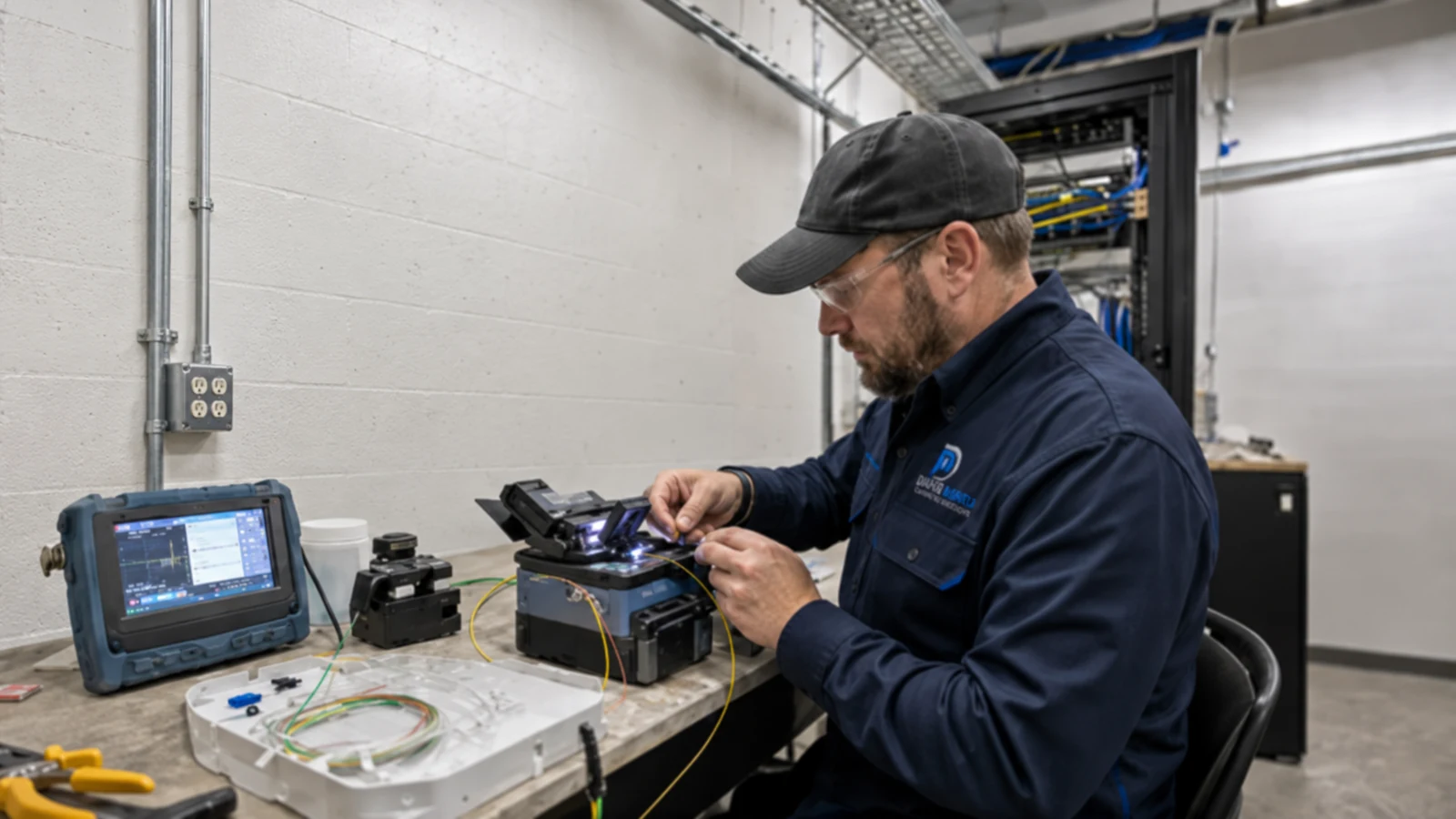
Commercial fiber work can include backbone or building-to-building cable, single-mode or multimode selection, strand-count planning, pathway review, pulling, splicing or connector termination, enclosures, labeling and optical testing. Fiber provides the passive optical path; switches, transceivers and network configuration remain separate network responsibilities unless included.
Single-mode and multimode fiber use different optics and application ranges. Selecting cable without the equipment strategy can create an avoidable compatibility problem.
A backbone sized only for today can consume all strands immediately. Spare capacity is inexpensive compared with opening the same pathway again.
Pull tension, bend radius, enclosure protection and pathway conditions matter during installation because fiber can be damaged without obvious external signs.
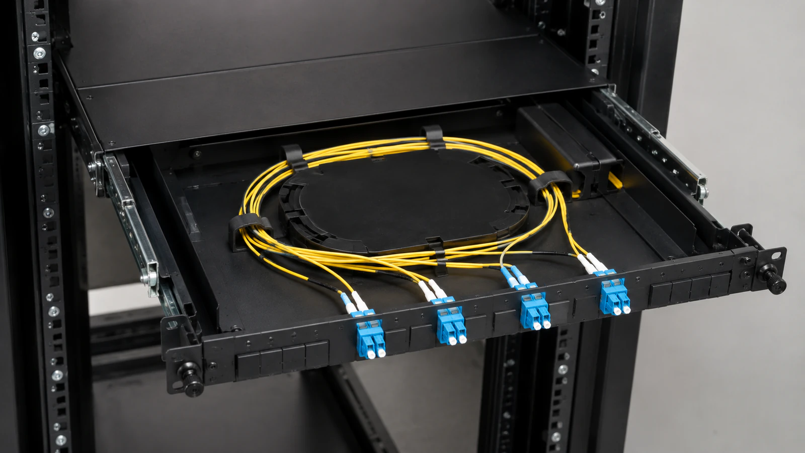
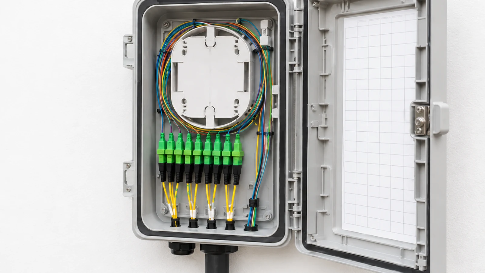
Splices, connector types, polarity and enclosure organization should be consistent so technicians can identify and service the link later.
A visible light check or link light alone does not document optical performance. The testing method should match the acceptance requirement for the installed link.
Without clear strand numbers, endpoints and test records, a multi-strand backbone becomes difficult to patch, troubleshoot or expand.
Choose single-mode or multimode based on distance, optics, application and the customer network strategy.
Allocate active strands and reasonable spare capacity for growth, redundancy or future services before cable selection.
Review pathway, pull length, bend radius, entrance points and enclosure locations so the cable is protected throughout the route.
Use appropriate splice trays, connectors, cassettes or patch panels and keep polarity and strand organization consistent.
Use the agreed optical test method and save results so the owner has evidence of link condition at handoff.
Label both ends, strand numbers, enclosure ports and test files so future network work can identify the correct fibers.
Fiber can connect an MDF to remote IDFs when distance or uplink capacity makes copper unsuitable.
Property campuses can use protected fiber pathways between buildings for network, security or other Ethernet-based systems.
Multi-building sites benefit from a consistent backbone strategy that identifies routes, enclosures and spare capacity by building.
High-capacity switch uplinks may use fiber even within one building when the network design requires optical interfaces.
Spare strands provide options for future services or replacement without immediately repulling the backbone.
Standard labels and test records make it easier to patch and troubleshoot fiber across several telecom rooms or buildings.
Confirm the two endpoints, route distance and the transceiver or application strategy that will use the link.
Select single-mode or multimode and enough strands for active use, redundancy and reasonable future needs.
Inspect conduit, innerduct, trays, pull points, entrances and bends before installation so pulling limits can be respected.
Define enclosure, splice, cassette and connector requirements at both ends, including polarity and patching expectations.
Agree on insertion-loss, OTDR or other test requirements appropriate to the link and acceptance criteria.
Identify whether optics, switch ports and network configuration are part of this scope or remain with the customer/IT team.
Fiber commonly provides the backbone that Network Infrastructure uses for switch uplinks between telecom rooms or buildings. Structured Cabling may begin at those remote IDFs for endpoint connections. The fiber scope should clearly separate the passive optical link from transceiver selection, switch configuration and network routing unless those items are explicitly included.
For Orlando commercial sites, fiber is often considered when telecom rooms are separated by long distances or buildings need a protected high-capacity backbone. The correct choice still depends on the actual route, endpoints, optics and pathway conditions at the property.
Use the Solutions hub when fiber is one part of a larger cabling or network project and system ownership needs to be coordinated.
A fiber site survey can confirm route length, conduit, pull points, enclosure locations and existing fiber before cable type and strand count are finalized.
Network Infrastructure is the related active scope that provides switches, optics, VLANs and uplink configuration for the passive fiber backbone.
Single-building offices may use fiber for MDF-to-IDF uplinks; managed properties may connect separate buildings; larger campuses may require multiple routes and spare capacity. Distance and network architecture determine where optical backbone infrastructure adds value.
Confirm the endpoints, route, distance, existing pathways and network application that will use the fiber.
Select fiber type, strand count, enclosures, termination method and test requirement, including reasonable spare capacity.
Pull the fiber using appropriate handling, then splice or terminate, organize enclosures and label both ends and strands.
Perform the agreed optical tests, correct failed links and deliver strand maps and test results for handoff.
Cameras Orlando is operated by Data Pro Communications. Florida low-voltage work is performed under FL License #EC13016138. Final recommendations depend on the approved scope, site conditions and the responsibilities stated in the project documents.
Fiber is typically considered for longer distances, building-to-building links, high-capacity backbones or environments where an optical link is preferable to copper. The network application still determines the final choice.
The choice depends on distance, transceivers, network speed and long-term strategy. Single-mode is common for longer-distance and future-capacity needs; multimode may fit shorter links with compatible optics.
Install enough for the current application plus reasonable spare capacity for growth, redundancy or future services. The right count depends on the network design and cost of accessing the pathway again.
Possibly. Existing fiber should be identified by type, strand count, termination and route, then tested to confirm the strands needed for the new application are usable.
Splicing joins fiber strands, often inside a protected tray; connector termination provides a pluggable interface for patching. Many commercial backbones use splices to pigtails or cassette-based termination.
Testing should match the acceptance requirement and may include insertion-loss measurements, OTDR traces or both. Saved results should identify the tested strand and endpoints.
Excessive bending can increase loss or damage the cable. Pathways, pull points and enclosure routing should respect the manufacturer and cable-design limits.
Not automatically. Fiber service can provide the passive optical backbone; switches, transceivers and network configuration belong to the active network scope unless specifically included.
Both ends should identify the cable, enclosure/port and strand or pair so patching and test records can be matched to the physical link.
It should verify endpoints, route distance, pathway condition, pull points, enclosure locations, existing fiber and the active-network requirements that will use the link.
Send the two endpoint locations, approximate distance and any existing pathway or network information. A field review can confirm fiber type, strand count, route, termination and testing requirements.