
Camera and Network Design Together
IP camera streams are planned with Ethernet pathways, PoE, switching, bandwidth and recorder/VMS capacity as one coordinated surveillance architecture.
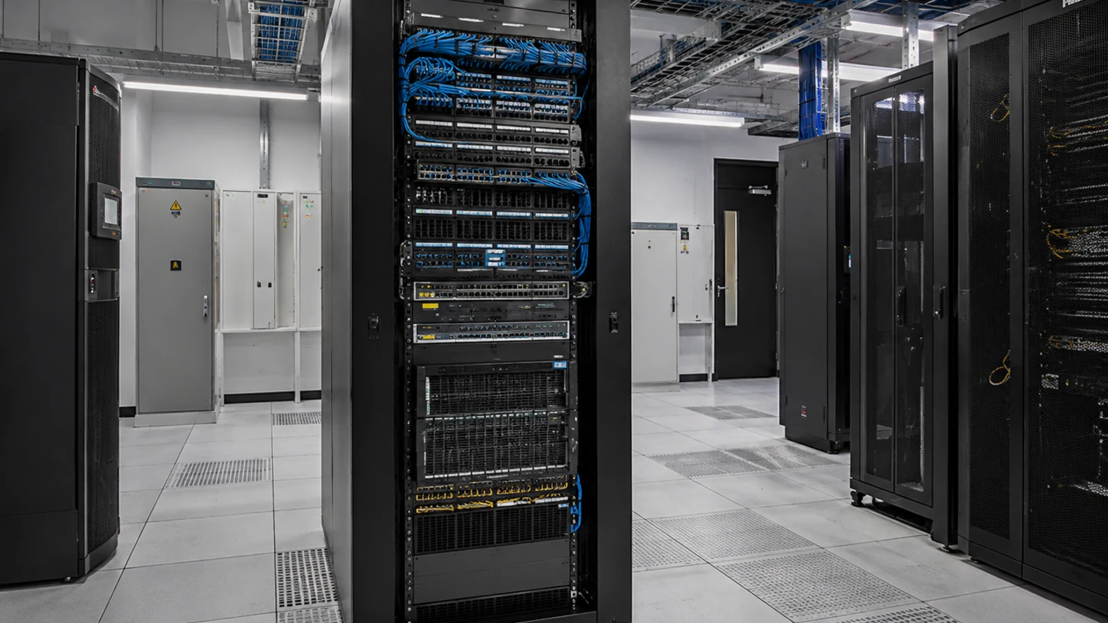
Network-Based Commercial Video Surveillance
IP video surveillance treats cameras as network devices. Camera streams travel over Ethernet through PoE switches to an NVR, VMS or other supported recording platform, so switching, bandwidth, addressing, storage and permissions are part of the surveillance design.
For Orlando commercial properties, an IP system can scale more flexibly than many legacy architectures, but only when the network and recording platform are sized for the camera count, stream settings and user workflow. Customer-managed cybersecurity and firewall responsibilities should be defined rather than assumed.
IP camera streams are planned with Ethernet pathways, PoE, switching, bandwidth and recorder/VMS capacity as one coordinated surveillance architecture.
Data Pro Communications operates under FL License #EC13016138.
Customer-managed VLANs, firewall policy, internet connectivity and account responsibilities are identified so surveillance configuration does not blur into undocumented IT ownership.
An IP camera project combines visual coverage with Ethernet pathways, PoE, switching, bandwidth, addressing, recorder/VMS capacity and user permissions. Each layer should support the final camera streams instead of being sized independently.
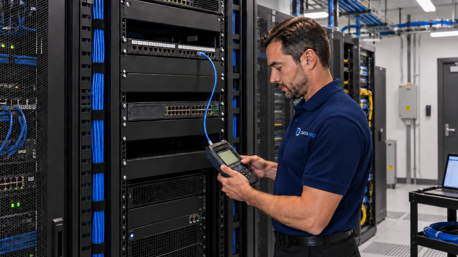
Without clear addressing and network ownership, camera discovery, troubleshooting and access control become harder as the system grows.
Camera streams can overwhelm switch uplinks or shared links when aggregate bitrate is ignored, causing dropped video or inconsistent recording.
A switch may have enough open ports but not enough total PoE budget for all cameras and peak device loads.
Basic connectivity does not guarantee full feature support. Camera streams, codecs, ONVIF profiles and VMS integrations should be checked against the selected platform.
Resolution, frame rate, codec, scene activity and recording mode can change bitrate dramatically. Retention should be calculated from actual stream assumptions.
Shared accounts or exposed recorder ports create avoidable risk. Remote access should use supported methods, named users and customer-approved network security practices.
Select switches with the port count, per-port power and total PoE budget required by the cameras, while leaving practical reserve for startup and future service.
A defined camera network or VLAN can simplify addressing, traffic separation and troubleshooting when it aligns with the customer’s network policy.
Use expected camera streams, codecs, frame rates and viewing patterns to size switch uplinks and recording connections.
Verify supported models, ONVIF profiles, stream settings, licenses and required features between cameras and the NVR or VMS.
Calculate usable storage from camera bitrates, recording mode and retention goals, including RAID or platform overhead where applicable.
Create named roles and permissions on the surveillance platform and coordinate remote connectivity with the customer’s network or cybersecurity owner.
Ethernet and PoE can combine camera data and power on structured pathways, simplifying deployment when switching and telecom spaces are planned correctly.
IP architecture can connect cameras across fiber-backed networks or multiple switches, provided uplinks, addressing and recorder connectivity are designed for aggregate traffic.
Large camera counts require deliberate PoE budgets, switch placement, uplink capacity and storage calculations rather than a single central cable bundle.
VMS environments may require server resources, camera licenses, supported profiles and role-based permissions in addition to camera hardware.
IP systems can support secure remote viewing when internet access, account ownership, firewall policy and supported connectivity are coordinated with the customer.
A documented IP addressing, switching and recording architecture makes it easier to add cameras later without redesigning the entire network each time.
Confirm cable category, distance, pathway and telecom-room termination for each planned camera before switch placement is finalized.
Add each camera’s expected power draw and verify both per-port capability and total switch power, including reasonable reserve.
Estimate aggregate camera traffic at each switch and confirm uplinks can carry recording and viewing traffic without avoidable bottlenecks.
Coordinate VLANs, subnets, DHCP/static addressing and firewall requirements with the customer’s network owner where surveillance uses shared infrastructure.
Check supported camera streams, licenses, processing, usable storage and retention for the selected NVR or VMS.
Identify who owns administrative credentials, remote connectivity, password policy and ongoing network changes after handoff.
IP video often shares physical network infrastructure while remaining a separate operational system. The design should identify which switches, VLANs, firewall rules and user accounts are customer-owned and which surveillance settings are part of the camera scope.
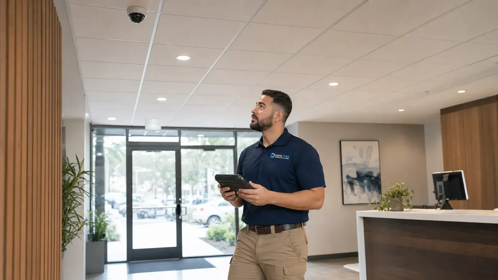
Orlando properties with multiple telecom rooms, detached buildings or long cable paths may require distributed PoE switching or fiber-backed uplinks. Those network decisions should follow measured distance and camera traffic at the actual property.
The Camera Services hub helps compare IP video with CCTV modernization, NVR/remote viewing, analytics and other camera services.
A site survey is useful when cable pathways, switch locations, fiber uplinks or network ownership must be verified before design.
Network Infrastructure is directly relevant when surveillance requires new PoE switching, VLANs, uplink capacity or secure connectivity.
An office with 12 cameras on one switch and a warehouse with cameras distributed across several IDFs are both IP surveillance projects, but their switching, bandwidth and storage architecture can be very different.
Identify camera views, Ethernet pathways, telecom rooms, customer network ownership, retention and remote-access requirements.
Size PoE switches, uplinks, addressing, NVR/VMS capacity and storage from the planned camera streams and system features.
Install and terminate cabling, connect cameras and switches, enroll devices in the recorder/VMS and apply the approved network configuration.
Verify stream stability, recording, playback, time synchronization, permissions and remote access where included, then document network and account ownership boundaries.
Cameras Orlando is operated by Data Pro Communications. Florida low-voltage work is performed under FL License #EC13016138. Final recommendations depend on the approved scope, site conditions and the responsibilities stated in the project documents.
Not always, but a dedicated surveillance VLAN or separate switching environment can improve traffic management, addressing and troubleshooting. The design should follow the customer’s network policy.
PoE determines where cameras can receive power over Ethernet. Switches must have enough compatible ports, per-port power and total PoE budget for all connected cameras.
Existing Cat5e or Cat6 may be reusable if the runs are within distance limits, properly terminated and in suitable condition. Each reuse candidate should be tested.
Bandwidth depends on resolution, frame rate, codec, scene activity and stream settings. Aggregate traffic should be estimated for each switch uplink and recorder connection.
Retention depends on camera bitrates, recording schedule or motion mode, camera count and usable storage capacity. Higher bitrates generally require more storage for the same number of days.
The NVR or VMS receives and manages camera streams, recording, playback, users and often remote access or analytics. Capacity and licensing must support the planned cameras and features.
No. ONVIF can improve interoperability, but supported profiles and specific features still need to be verified between the camera and recording platform.
Yes, when the recorder/VMS and network are configured for a supported secure remote-access method. User accounts, permissions and customer cybersecurity policy should be defined.
Many commercial systems use controlled static addressing or reservations so devices remain predictable. The exact method should align with the customer’s network management approach.
Verify every camera stream, PoE stability, recording, playback, time synchronization, naming, permissions, remote access where included and representative exports.
Share the planned camera count, property layout, existing Ethernet or fiber infrastructure and recording goals. We can use those details to evaluate PoE switching, bandwidth, recorder/VMS capacity and the network responsibilities that affect the IP design.