
Commercial-First Planning
Cabling work is planned as a permanent pathway-and-termination system, not simply a cable pull from point A to point B.
Commercial Low-Voltage and Security Systems
Structured cabling is the permanent copper infrastructure that connects work areas and low-voltage devices back to telecom rooms. A commercial cabling project should define cable category, pathway, termination points, rack or patch-panel layout, labeling and the test standard before large quantities are pulled.
For Orlando businesses, Cat6 is common for many data, voice, camera and access-point applications; Cat6A may be appropriate when the application, distance, PoE load or future performance target justifies it. The choice should match the actual channel and device requirements.
Cabling work is planned as a permanent pathway-and-termination system, not simply a cable pull from point A to point B.
Data Pro Communications operates under FL License #EC13016138.
Labels, patch-panel records and test results help owners and IT teams identify and support each installed link after handoff.
Structured cabling includes horizontal copper runs, pathways, patch panels, jacks or device-side terminations, rack organization, labeling and testing. It creates the physical layer used by switches, computers, phones, access points, IP cameras and other Ethernet devices without taking ownership of the active network design.
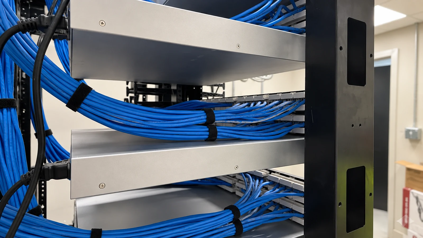
Ceiling access, sleeves, conduit fill, fire-rated assemblies and route length can make a theoretical cable path impractical. Pathways should be reviewed before pull quantities are committed.
Cat6 and Cat6A differ in size, handling and performance. The category should be selected for the intended application rather than as a generic upgrade.
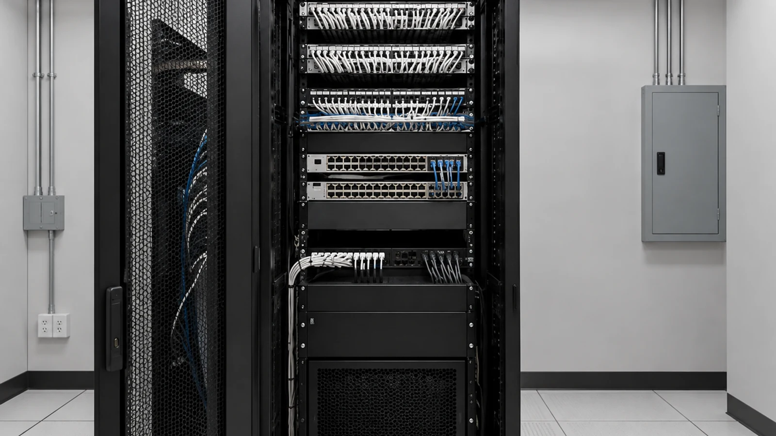
Patch-panel space, rack units, cable management, grounding/bonding responsibilities and switch adjacency can affect how cleanly new links terminate in an MDF or IDF.
A cable that is labeled differently at the jack and patch panel creates avoidable troubleshooting time. Labels should use one naming convention across drawings and field work.
Continuity alone does not prove a permanent copper link meets its category. Certification requirements should be identified when category performance must be documented.
Moves during construction can make drawings and port schedules stale. Final records should match the installed jack, patch-panel and room identifiers.
Map each work-area or device location to the correct MDF/IDF and verify the route stays within practical copper distance and pathway limits.
Match cable category and components to the application, environment and expected performance instead of mixing incompatible channel parts.
Terminate permanent links on organized patch panels or approved device-side hardware with appropriate cable management.
Use a consistent identifier from outlet or device location through the patch panel so IT can trace the link without guesswork.
Test and, when required, certify each installed permanent link to the agreed category and record failures that need correction.
Provide port schedules, labels and test records that reflect the final installed locations.
Office cabling supports desks, phones, printers, conference rooms and other Ethernet endpoints through permanent links back to the telecom room.
Managed properties may use structured cabling for IP cameras, wireless access points, access-control panels or other networked devices where copper distance is appropriate.
Larger properties often distribute IDFs so horizontal links remain practical and do not exceed copper-channel limitations.
A consistent patching and label scheme makes future workstation moves and device changes easier without altering the permanent cable unnecessarily.
Property portfolios benefit from standardized room, patch-panel and outlet identifiers so service teams can locate links across sites.
Using the same approved test method across buildings creates comparable records while still allowing different cable categories where applications require them.
Confirm route length, pathway accessibility, conduit or sleeve conditions and the MDF/IDF serving each endpoint before pulling cable.
Use compatible cable, jacks, patch panels and termination methods for the selected category and environment.
Check rack space, patch-panel capacity, cable management and the relationship to active network equipment supplied by the customer or network scope.
Define whether the endpoint terminates on a jack, patch panel, plug or device-specific connector and keep both ends within the approved channel design.
Specify whether basic wiremap, qualification or full category certification is required and how test records will be delivered.
Maintain a final port schedule that links endpoint identifiers to patch-panel ports, room names and test results.
Structured cabling is the physical layer for many other W3 solutions, but it is not the same as the active network. Cabling can provide copper links for switches, access points, cameras, controllers and AV devices; network configuration, device programming and application behavior remain separate responsibilities unless included in those scopes.
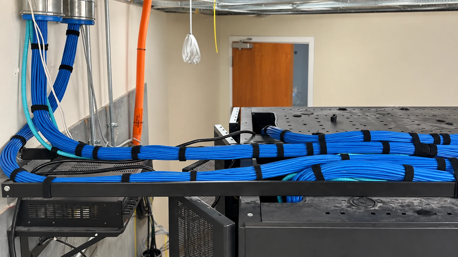
Orlando commercial properties often add or modify data drops as spaces change, but the durable value comes from organized pathways, telecom-room terminations, labels and test records. Existing cable can be considered for reuse only when its route, condition, category and test results support the new application.
The Solutions hub helps when structured cabling is part of a larger project with network, fiber or other building systems.
A cabling site survey can confirm pathways, telecom rooms, cable distances and the condition of existing links before quantities are finalized.
Network Infrastructure is the related active-system scope for switching, VLANs, PoE capacity, routing and uplinks that use the installed cabling.
Offices may focus on work-area density and moves; managed properties may cable cameras and access points; larger facilities may need multiple IDFs or fiber between rooms. Those differences affect pathway design and where copper cabling should begin and end.
Confirm endpoint locations, MDF/IDF assignments, pathways, cable category and any existing links proposed for reuse.
Build the cable schedule, route plan, patch-panel layout, label convention and test requirement before pulling.
Pull and dress the cable, terminate both ends, label the installed links and keep telecom-room organization consistent with the approved plan.
Test each link, correct failures and provide the final port schedule and test records for handoff.
Data Pro Communications - South Orlando is operated by Data Pro Communications. Florida low-voltage work is performed under FL License #EC13016138. Final recommendations depend on the approved scope, site conditions and the responsibilities stated in the project documents.
Cat6 is appropriate for many commercial Ethernet applications. Cat6A may be selected when the application, PoE load, channel performance or future requirements justify the larger cable and related components.
Possibly. Reuse should be based on cable category, route, length, physical condition, termination quality and test results, not just the fact that the cable currently passes traffic.
An MDF or IDF is the telecom room where horizontal cabling terminates on patch panels and connects to active network equipment. Larger sites use multiple rooms to keep cable distances and pathways manageable.
Each link should use the same identifier at the endpoint and patch panel, tied to a port schedule or drawing that identifies the room and location.
When category performance must be documented, certification testing should verify the permanent link against the selected cabling standard and provide saved test results for each cable.
Commercial balanced copper channels have standards-based distance limits. The pathway and telecom-room layout should be planned so the permanent link and patch cords remain within the applicable channel design.
Yes. Properly designed copper links can provide Ethernet and PoE connectivity for cameras, access points and other network devices when distance and power requirements are within the supported design.
Not automatically. Structured cabling covers the physical links and terminations; switching, VLANs, routing and other active-network configuration belong to the network scope unless specifically included.
Useful handoff records include outlet or device labels, patch-panel ports, room identifiers, cable category and saved test results.
It should verify endpoint locations, MDF/IDF rooms, pathways, route distance, ceiling or conduit conditions, rack capacity and any existing cable proposed for reuse.
Send the endpoint count, property layout and MDF/IDF information you have. A cabling site survey can confirm routes, cable category, terminations and testing requirements before installation quantities are locked.