
Commercial-First Planning
Projects are planned around property operations, infrastructure and the people responsible for the system.
Commercial Camera Resource | Integrated systems
Coordinated planning aligns pathways, equipment rooms, power, network segmentation, door-event interfaces and testing before separate trades make conflicting assumptions. The systems can share infrastructure without sharing every credential or failure domain.
A controlled staff door can pair an access event with a nearby camera when system clocks and permissions are aligned. Coordination reduces duplicate pathways and change orders, but combining systems without clear ownership can expand outages and administrative access.
Projects are planned around property operations, infrastructure and the people responsible for the system.
Data Pro Communications operates under FL License #EC13016138.
Testing, labeling, credentials and known limitations are organized for the people who will operate and support the system.
Coordinated planning aligns pathways, equipment rooms, power, network segmentation, door-event interfaces and testing before separate trades make conflicting assumptions. The systems can share infrastructure without sharing every credential or failure domain.
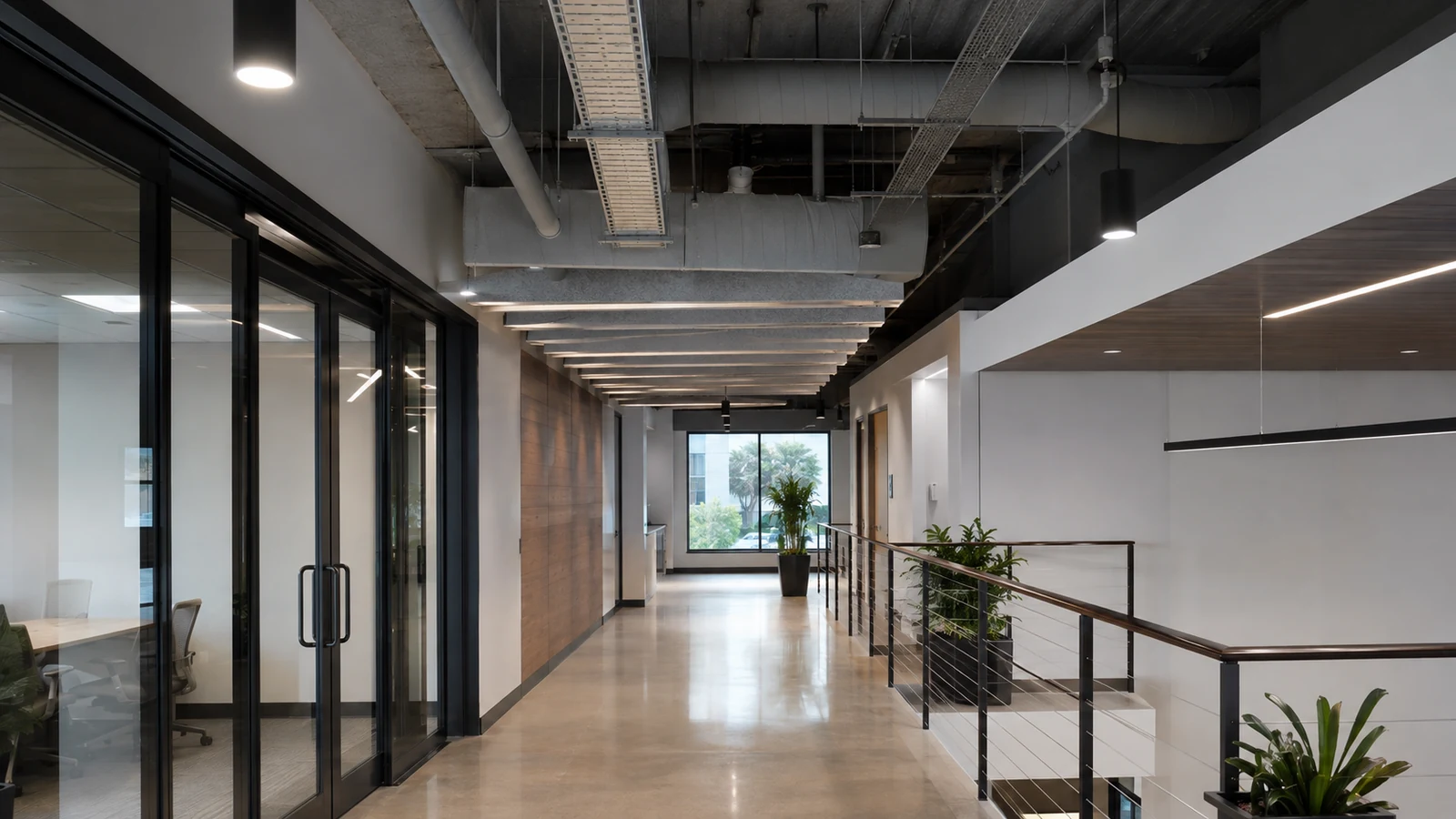
Shared pathway capacity and separation requirements can affect camera cabling when other building systems already occupy the route.
Poor segmentation can expose camera traffic to unrelated congestion or create unnecessary administrative and security risk.
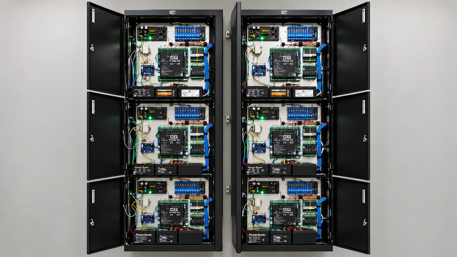
Add the camera, lock, reader and network loads that share backup power, then verify circuit and UPS capacity for the operating state the property expects during an outage.
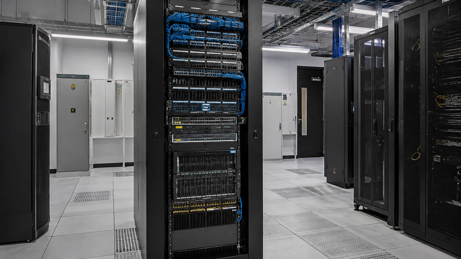
Shared MDF/IDF space can become a project constraint when rack space, power, switch ports, patching or cable entry are not coordinated before installation.
An event may fail to trigger the expected video or access workflow when the data exchanged, network path or failure behavior between systems is not defined.
Testing cameras and access control separately can miss timestamp, permission and event-link problems at the shared workflow.
Check available pathway capacity and separation needs before adding camera cabling beside other building systems.
Verify the intended VLANs, routing and management access for cameras and adjacent building systems so required traffic passes without unnecessary exposure.
Calculate power planning from device class, startup and auxiliary load, switch or local capacity, cable loss and backup-power requirements; then test a restart.
Confirm rack space, power, patching, switch ports and cable entry in each equipment room before camera, access-control and network work compete for the same infrastructure.
Test the actual event or data exchanged between systems, including time alignment and failure behavior, rather than validating each platform only in isolation.
Verify camera recording, access-control events, switch connectivity and shared power under the same operating sequence so an interface problem is visible before closeout.
A controlled staff door can pair an access event with a nearby camera when system clocks and permissions are aligned.
A shared telecom room can support camera and access switches on separate VLANs and UPS circuits with documented port ownership.
A new buildout can coordinate camera, access-control and data pathways before ceilings close, but rack space, power and system ownership still need explicit allocation. Allocate camera and door-device power, rack space and pathways before ceilings close, including backup power for the systems that must remain available.
An occupied retrofit requires agreed work windows, protected pathways and a sequence that preserves building access and business operations. Coordinate occupied access, finished surfaces and shutdown windows while keeping camera, access-control and network changes traceable.
Segmentation should define camera, recorder and management traffic, permitted remote access and the owner of firewall and switching changes. Define VLANs, uplinks, time synchronization and permissions so video and door events can be compared without exposing administration broadly.
Coordinated testing should verify each system independently before checking timestamps, door events, video retrieval and failure behavior across the interface. Test camera, access-control and cabling functions separately, then verify the actual door event, timestamp, associated view and failure behavior.
Approval of shared pathways requires route length, test results, protection, termination, environmental exposure and service access, plus a test result appropriate to the copper or fiber medium.
Keep cameras, access control and other building systems on deliberate network segments with documented routing and management access so one change does not unintentionally expose or isolate another system.
Engineering inputs for power planning include device power class, startup load, switch budget, cable loss, backup power and port behavior; confirm both per-port and total capacity and document restart behavior.
Coordinate rack space, power, switch ports, patching and cable entry in the MDF/IDF before separate trades install equipment that depends on the same room.
For each camera/access/network interaction, identify the event or data exchanged, the network path and the expected behavior when one side is unavailable.
Verify each system on its own, then test the real door event, associated video, time alignment, user permissions and behavior when an interface is unavailable.
The operating workflow for coordinated camera, access-control and cabling design may rely on network segmentation, power planning and equipment rooms. Define which team owns configuration, connectivity and event response so a system alert reaches someone able to act.
At an Orlando commercial property, cameras, access control and network cabling should be coordinated wherever they share pathways, telecom rooms, switches, power or administrative ownership. Planning those dependencies together can prevent one scope from consuming capacity or access that another system was expected to use.
Separate guides on structured cabling, PoE, network segmentation and access control provide deeper detail on the shared infrastructure described here.
Camera Services defines the camera and recording work while access-control, cabling and network owners handle their portions of the coordinated design.
A coordinated site review is useful when equipment-room capacity, pathways or interface ownership cannot be assigned from existing plans.
The operating model succeeds when ownership for shared pathways, network segmentation and power planning is clear and the records represented by system interfaces and coordinated testing remain usable after handoff.
Identify where camera, access-control and data cabling share pathways or equipment spaces and confirm there is physical capacity for the planned work. Shared infrastructure should be coordinated before separate trades occupy the same route.
Document which system supplies device power, which switches or VLANs carry traffic and who administers the network and security platforms. Clear boundaries reduce troubleshooting disputes when one system depends on another team's equipment.
Identify any camera-to-access events, door-triggered video, shared credentials or other real integrations and confirm both platforms support the required behavior. Do not create integration scope merely because systems are installed in the same building.
Verify cameras, doors and cabling independently before testing any cross-system event. If an integrated workflow fails, this sequence makes it easier to identify whether the problem is in a device, network path or application interface.
Cameras Orlando is operated by Data Pro Communications. Florida low-voltage work is performed under FL License #EC13016138.
For shared pathways, trace and label the route, inspect protection and termination, measure distance, use the appropriate copper or fiber test and confirm future service access.
Confirm that cameras can reach the approved recorder and management services while unauthorized networks cannot reach camera administration. Test the VLAN and access rules with representative camera traffic and the intended support accounts.
For power planning, add device and auxiliary load, compare it with switch or local-power capacity, account for cable loss and backup power, and observe restart behavior in coordinated camera, access-control and cabling design.
Confirm rack space, power and UPS capacity, switching, patching, grounding, labeling, environmental conditions and ownership of each system connection.
For system interfaces, identify the owner on each side, interface or signal exchanged, timing and permissions, power and network boundary, failure behavior and acceptance test.
For coordinated testing, verify the visible scene or system function under representative operation, review recorded playback, complete an export, check authorized accounts and document exceptions.
They can share managed switching and pathways when segmentation, power, capacity, labeling and ownership are designed for both systems.
Matching timestamps lets operators compare door events with video during incident review and helps identify configuration drift.
The scope should identify the contractor responsible for pathway capacity, cable separation, rack space, power, patching, labeling and certification.
Test cameras, access control and cabling independently, then test the actual cross-system event, permissions, timing and failure behavior.
If ownership for shared pathways, network segmentation or power planning remains unclear, request a project review that includes the operating manager and the responsible IT or facilities contact.